
The downside of the old knob and tube style of wiring is that some off-the-shelf light switches, like the common Leviton motion-sensor switch, are totally non-functional without a ground wire — which knob and tube wiring doesn’t typically provide.
What is a hacker to do?
The smarter solution is probably to find a way to run a ground wire through the walls of half hour house and up two floors to go from your junction box to the switch in question.
My solution? Build my own.
The simplest way to cobble together a motion detector light would be something like a PIR sensor attached to a power supply and a relay to safely control mains voltage, but that has no way to manually activate or deactivate the light.
To add a bit more granular control to the system, I decided to build it on top of an Arduino base, so I could add more controls. For space constraints (as well as the fact that I had a spare one lying about), I used a Wemos D1 Mini — easily programmed via the Arduino IDE, and if I ever want to expand its capabilities, I can easily connect it to my home wifi and attach it to Blynk.
As an added bonus, I has a D1 Mini Relay Shield lying about as well. This made one less thing I needed to wire up, and could just plug it in. Add in a momentary switch for human input, and our circuit looks something like this:
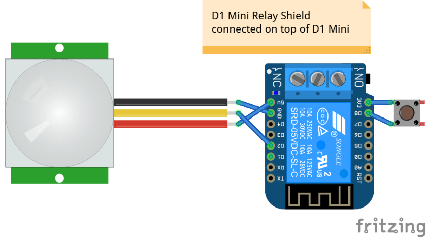
(Note, that is the relay shield stacked on top of the D1 Mini, they can be hard to differentiate in the mockup)
Bill of Materials:
- D1 Mini — $2.85
- D1 Mini Relay Shield — $1.36
- PIR Sensor — $0.78
- Momentary Switch — $1.76 (but I wound up using this $4.49 one from Home Depot)
- A little bit of wire.
After some tinkering, here is my code to get the system working:
This file contains hidden or bidirectional Unicode text that may be interpreted or compiled differently than what appears below. To review, open the file in an editor that reveals hidden Unicode characters.
Learn more about bidirectional Unicode characters
| /** | |
| * PIR Closet Sensor, with kill switch. | |
| */ | |
| const int relayPin = D1; | |
| const int pirSensor = D2; | |
| const int btnSensor = D8; | |
| int pir = 0; // Variable for pir. | |
| int pirState = LOW; // Start as off. | |
| int btn = 0; // Variable for button. | |
| int btnState = LOW; // Start as off. | |
| void setup() { | |
| Serial.begin( 9600 ); | |
| Serial.println(); | |
| Serial.println( "Starting up…" ); | |
| pinMode( relayPin, OUTPUT ); | |
| pinMode( pirSensor, INPUT ); | |
| pinMode( btnSensor, INPUT ); | |
| } | |
| void loop() { | |
| btn = digitalRead( btnSensor ); | |
| pir = digitalRead( pirSensor ); | |
| // If a button is pushed, and motion is detected, | |
| // turn off the light and wait until it resets. | |
| if ( HIGH == btn && LOW == btnState && HIGH == pir ) { | |
| digitalWrite( relayPin, LOW ); | |
| btnState = HIGH; | |
| Serial.println( "Killswitch detected — turning off light." ); | |
| delay( 1000 ); | |
| return; | |
| } | |
| // If the button was pressed, keep shorting | |
| // until the pir goes low again. | |
| if ( HIGH == btnState ) { | |
| if ( LOW == pir ) { | |
| Serial.println( "No motion, resetting state." ); | |
| btnState = LOW; | |
| } | |
| if ( HIGH == btn ) { | |
| Serial.println( "Button pressed, turning light back on." ); | |
| digitalWrite( relayPin, HIGH ); | |
| btnState = LOW; | |
| } | |
| return; | |
| } | |
| // If the pir senses light, | |
| if ( HIGH == pir ) { | |
| digitalWrite( relayPin, HIGH ); | |
| if ( LOW == pirState ) { | |
| Serial.println( "Motion detected!" ); | |
| pirState = HIGH; | |
| } | |
| } else { | |
| digitalWrite( relayPin, LOW ); | |
| if ( HIGH == pirState ) { | |
| Serial.println( "Motion ended." ); | |
| pirState = LOW; | |
| } | |
| } | |
| } |
The code could probably be simplified by removing the logging messages, but I like to leave them there for further reference and debugging down the road.
So now that we’ve got the components gathered, it’s time to look at how we put it in! As luck would have it, the electrical box that the previous switch used was a double gang box, so I had a bit of room to work with. I picked up a solid 2-gang cover at my local Home Depot, and drilled two holes in it for the switch and the PIR sensor.
Now, all is right with the world, but we still have to actually power it! Through some creative wiring, we’ve thus far managed to avoid having to splice any wires together (by using both the 5v and 3v3 outs on the board for wiring to different peripherals, and only the PIR needed a ground wire) and to continue that trend, we’re going to be powering it through the D1 Mini’s USB port, and to power that USB port via a 6″ USB cable, connected to a genuine Apple iPhone power adapter — they’re tiny, and very well built transformers (just don’t mess around with cheap knockoffs, they’re terrifyingly dangerous — especially if it’s going to be mounted inside a wall!).
To connect the 120v AC to 5v DC transformer (the aforementioned power adapter) to mains power, my plan is to connect it to home wiring via two crimp terminals and some heat-shrink tubing around that as additional insulation to avoid any exposed metal, as there isn’t an outlet in the box to plug the adapter into.
Well, that’s the plan. As I said — far trickier than just running a ground wire across half my house, but hopefully more fun and I’ve learned a lot in the process. I’m expecting to hook it up in the next couple days, and will update here when it’s live and functioning!
